MCS catalog began delivering technical reference information and charts over twenty years ago. Today we continue that service as part of our commitment to provide contractors with “Solid Support”.
Included here are forming tips, material usage charts and metric-English conversion information. In the future, this section will continue to grow please let us know of any additional information or industry links you may find useful.
This section is divided into five areas
- Reference Information
- Manufacturers We Represent
- Manufacturer’s Information Links
- Conversion Tables
- Line Card
Reference Information
- Bending Radius for Plywood Panels
- Concrete Requirements for Round Column Forms
- Concrete Requirements for Walls of Slabs
- Curb and Gutter Expansion Joint Ordering Guide
- The Eleven Hole Pattern
- Plastic Chamfer Strip Dimension Guide
- Radius Forming Notes
- Sealant Usage Chart
- Single Waler System Forming Notes
Bending Radius
| Minimum Bending Radius for Plywood Panels* | ||
| Panel Thickness | Curved Across Grain | Curved Parallel to Grain |
|---|---|---|
| 1/4″ | 2′-0″ | 5′-0″ |
| 3/8″ | 3′-0″ | 8′-0″ |
| 1/2″ | 6′-0″ | 12′-0″ |
| 5/8″ | 8′-0″ | 16′-0″ |
| 3/4″ | 12′-0″ | 20′-0″ |
| *Suggested by ACISP-4 for average work based on information supplied by APA. Laminate thin plywood sheets to insure nexessary strangth on short radius work. |
||
Concrete Requirement Charts
| For round columns | ||||||
|---|---|---|---|---|---|---|
| Column Diameter in Inches | 10 | 12 | 14 | 16 | 18 | 20 |
| Cubic Yards of concrete per foot of Height | 0.0202 | 0.0297 | 0.0396 | 0.0517 | 0.0654 | 0.0808 |
| Column Diameter in Inches | 22 | 24 | 30 | 36 | 42 | 48 |
| Cubic Yards of concrete per foot of Height | 0.0978 | 0.1164 | 0.1818 | 0.2618 | 0.3563 | 0.4654 |
| For walls and slabs | ||||||
|---|---|---|---|---|---|---|
| Concrete Thickness in Inches | 1 | 2 | 3 | 4 | 4.5 | 5 |
| Square Foot Yield per Cubic Yard | 324 | 152 | 108 | 81 | 72 | 64.8 |
| Concrete Thickness in Inches | 5.5 | 6 | 6.5 | 7 | 7.5 | 8 |
| Square Foot Yield per Cubic Yard | 58.9 | 54 | 49.8 | 46.3 | 43.2 | 40.5 |
Curb & Gutter Expansion Joint Ordering Guide
Use this guide to order custom fibre expansion joint.
Click here to download an order form in PDF format. 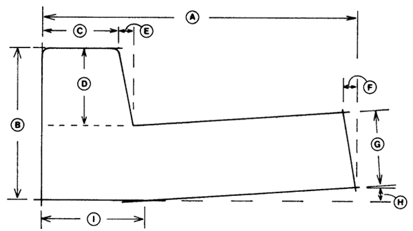
The Eleven Hole Pattern
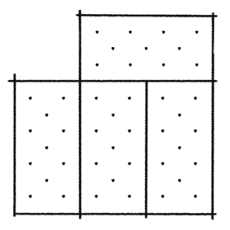 A simple application of the single waler system utilizes the eleven hole drilling system as illustrated. Notice that tie holes line up whether sheets are placed horizontally or vertically. This allows for gang drilling of the plywood. The eleven hole pattern provides consistent 12″ vertical spacing for walers and 24″ horizontal spacing for ties. Each tie covers approximately 3 sq. ft. of form surface, staying well within the safe working load of the system. The eleven hole drilling pattern combined with single waler hardware and the Sansoe flat end snaptie provides a simple, efficient forming system ideal for bank vaults, retaining walls, foundations and many other applications.
Plastic Chamfer Strip
 |
Radius Chamfer Strip Type RFN |
|
| Cat. No. | “A” dimen. | “REF” dimen. |
| 602 | 1/2″ | 3/8″ |
| 603 | 3/4″ | 9/16″ |
| 604 | 1″ | 3/4″ |
| 605 | 1-1/2″ | 1-1/4″ |
 |
Chamfer Strip Type CSN |
|
| Cat. No. | “A” dimen. | “REF” dimen. |
| 611 | 1/2″ | 2-3/32″ |
| 612 | 3/4″ | 1-1/16″ |
| 613 | 1″ | 1-13/32″ |
| 614 | 1-1/2″ | 2-1/8″ |
 |
Chamfer Strip Type CS |
|
| Cat. No. | “A” dimen. | “REF” dimen. |
| 621 | 1/2″ | 2-3/32″ |
| 622 | 3/4″ | 1-1/16″ |
| 623 | 1″ | 1-13/32″ |
| 624 | 1-1/2″ | 2-1/8″ |
Radius Forming Notes
MCS recommends a system for radius forming involving “A” brackets, snapties, and-to avoid filler strips-trimmed interior plywood.
Tie Spacing
This special drilling layout allows single 2X4 stud coverage of vertical panel joint whether joint is continuous or panels are staggered. Caution: Be sure that holes drilled 1-1/8″ in from panel edge are to the right as shown, whether used on interior or exterior wall form. 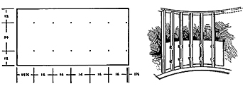
Plywood Trimming
To eliminate the need for exterior panel filler strips, plywood for the inside forms may be trimmed to compensate for the difference in circumference. Measure 1-1/8″ in from panel edge, and adjust spacing for subsequent holes accordingly. For heavy duty radius forming jobs, ask MCS for info on Gates Radius Forming Systems
Form Construction
- Using 1-1/8″
plywood, cut a template to conform to the desired radius (reduce
radius to compensate for thickness of studs and plywood). - Set back to
compensate for thickness of studs and plywood and nail tem- plate
to footing. - Toenail studs
to template. - Tack plywood
to first stud and install snapties and “A” brackets to secure
plywood to remaining studs. “A” brackets should always be set
on the left side of studs so eccentric is properly positioned
to be vibration-proof. - Temporarily
brace using adjustable form aligner braces. - Continue for
additional sheets, staggering plywood joints as panels are stacked. - Check and align
form; cut top template to conform to full radius minus plywood
thickness and nail template to top of form. - Double-up-outside
form will conform to the radius of the inside form.
Sealant Usage Chart
| Linear Feet per Gallon | ||||||
|---|---|---|---|---|---|---|
| 1/4 | 1/2 | 3/4 | 1 | 1-1/4 | 1-1/2 | |
| 1/4 | 308 | |||||
| 1/2 | 154 | 77 | ||||
| 3/4 | 102.7 | 51.3 | 34.2 | |||
| 1 | 77 | 38.5 | 25.7 | 19.3 | ||
| 1-1/4 | 61.6 | 30.8 | 20.5 | 15.4 | 12.3 | |
| 1-1/2 | 51.3 | 25.7 | 17.1 | 12.8 | 10.3 | 8.6 |
Single Waler System Forming Notes
 |
1. Footing |
 |
2. Place Panels |
 |
3. Install Hardware & Supports |
 |
4. Double Up |
|
Vertical Joint Design |
|
|
Strongback Detail |
|
|
Laced Corner Design |