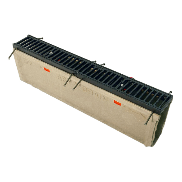
PolyDrain Channels

The PolyDrain Trench Drain System consists of 30 interlocking sloped channels and 4 non-sloped channels. Special non-sloping channels can be inserted at specified intervals in order to extend channel runs. Catch basins, horizontal outlet plates, closed end plates and vertical outlet plate adapters can be installed at designated locations. Closed end plates terminate channel runs. To determine number of channels required simply divide footage by 3.27.

PolyDrain channels are a nominal meter (39.19 in., 3.27 ft.) long. Standard channels have a 0.6% built in slope. The 30 standard channels are positioned sequentially in numerical order from 010 to 300, creating a continuously sloped channel run. With PolyDrain, runs of almost any length are possible by varying outlet placements, integrating non-sloping channels and using PolyWall Sidewall Extensions for increased depth. Channel runs can be designed with intersections or miters and fabricated onsite utilizing commercial grade cutting tools.

Channel Specifications

Use this chart to estimate flow capacities and invert elevations. Add a minimum of 4” to overall depths to estimate necessary excavation or as recommended by Structural Engineer. Actual depth of excavation is governed by slab or pavement thickness. When using the Model 510 Series frame and grate systems, add 1.2 in. (31 mm) to the overall depths.

Available Products

Part No. Channel Only
Overall Channel Dept in. (cm) Maximum Flow Rate gpm (lpm) Weight lbs (kg)
Minimum Maximum
010 5.1 (12.9) 5.3 (13.5) 106.7 (403.8) 31.1 (14.1)
020 5.3 (13.5) 5.6 (14.1) 115.8 (438.3) 32.8 (14.9)
021 5.6 (14.1) 5.6 (14.1) 32.0 (14.5)
030 5.6 (14.1) 5.8 (14.7 125.0 (473.1 33.6 (15.2
040 5.8 (14.7) 6.0 (15.3) 134.2 (508.0 34.3 (15.5)
050 6.0 (15.3) 6.3 (15.9) 143.5 (543.0) 33.8 (15.3)
060 6.3 (15.9) 6.5 (16.5) 152.7 (578.2) 35.2 (16.0)
070 6.5 (16.5) 6.7 (17.1) 162.1 (613.5) 36.2 (16.4)
080 6.7 (17.1) 7.0 (17.7) 171.4 (648.9) 37.0 (16.8)
090 7.0 (17.7) 7.2 (18.3) 180.8 (684.3) 38.0 (17.2)
091 7.2 (18.3) 7.2 (18.3) 37.4 (17.0)
096 7.2 (18.3) 7.2 (18.3) 20.1 (9.1)
100 7.2 (18.3) 7.4 (18.9) 190.2 (719.9) 37.6 (17.1)
110 7.4 (18.9) 7.7 (19.5) 199.6 (755.5) 39.8 (18.1)
120 7.7 (19.5) 7.9 (20.1) 209.0 (791.2) 40.6 (18.4)
130 7.9 (20.1) 8.2 (20.7) 218.5 (826.9) 42.4 (19.2)
140 8.2 (20.7) 8.4 (21.3) 227.9 (862.7) 42.8 (19.4)
150 8.4 (21.3) 8.6 (21.9) 237.4 (898.6) 42.6 (19.3)
160 8.6 (21.9) 8.9 (22.5) 246.9 (934.4) 44.2 (20.0)
170 8.9 (22.5) 9.1 (23.1) 256.3 (970.4) 45.1 (20.5)
180 9.1 (23.1) 9.3 (23.7) 265.8 (1006.3) 46.1 (20.9)
190 9.3 (23.7) 9.6 (24.3) 275.4 (1042.3) 46.8 (21.2)
191 9.6 (24.3) 9.6 (24.3) 46.6 (21.1)
200 9.6 (24.3) 9.8 (24.9) 284.9 (1078.3) 46.9 (21.3)
210 9.8 (24.9) 10.0 (25.5) 294.4 (1114.4) 48.6 (22.0)
220 10.0 (25.5) 10.3 ( 26.1) 303.9 (1150.5) 49.8 (22.6)
230 10.3 (26.1) 10.5 (26.7) 313.5 (1186.6) 50.0 (22.7)
240 10.5 (26.7) 10.7 (27.3) 323.0 (1222.7) 51.5 (23.4)
250 10.7 (27.3) 11.0 (27.9) 332.6 (1258.9) 50.5 (22.9)
260 11.0 (27.9) 11.2 (28.5) 342.1 (1295.0) 52.4 (23.7)
270 11.2 (28.5) 11.5 (29.1) 351.7 (1331.2) 53.0 (24.0
280 11.5 (29.1) 11.7 (29.7) 361.2 (1367.4) 54.5 (24.7)
290 11.7 (29.7) 11.9 (30.3) 370.8 (1403.6 54.9 (24.9)
291 11.9 (30.3) 11.9 (30.3) 53.4 (24.2)
300 11.9 (30.3) 12.2 (30.9) 380.4 (1439.9) 55.6 (25.3)


Download PolyDrain Catalog & Installation Instructions

Call for Questions 800-371-5225

Description

Pre-Sloped Radius Channels

Radius Channel

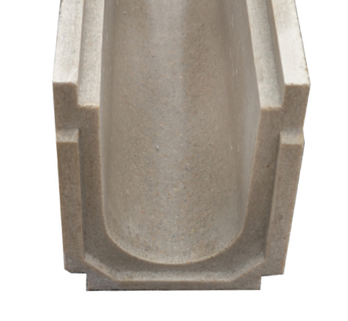
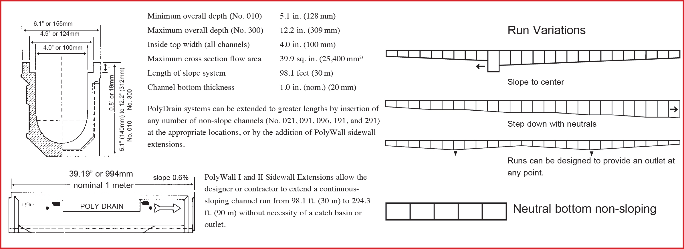
Standard PolyDrain channels have a builtin 0.6% slope with a smooth radius bottom and a narrow cross section. These features provide excellent hydraulic efficiency. Without any site slope, a 3.5 feet per second self-cleaning velocity is obtained when the channels are flowing full.

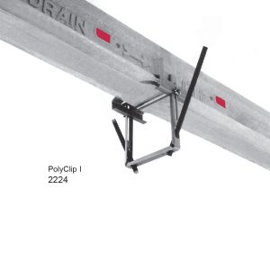
Independent Anchor Frame

Radius Channel

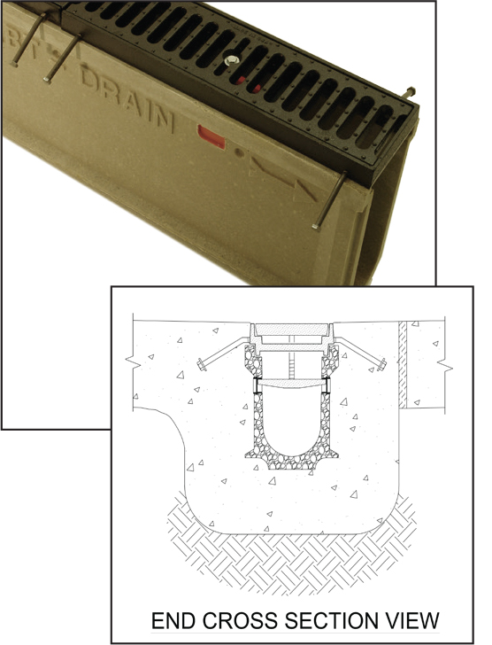
Independently anchored frames transfer the dynamic loads directly into the encapsulation concrete and channels are mechanically anchored via the full length rib. This eliminates the wheel load from creating strain on the channel and keeps the channel

PolyWall® Sidewall Extensions

Radius Channel

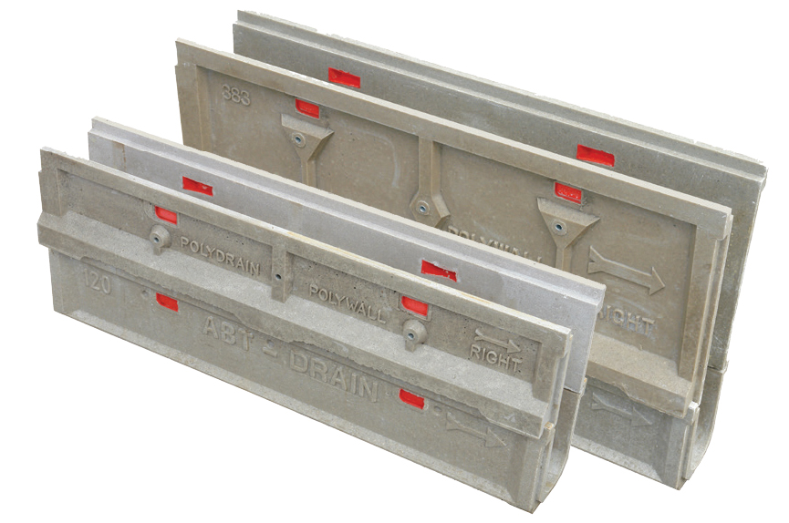
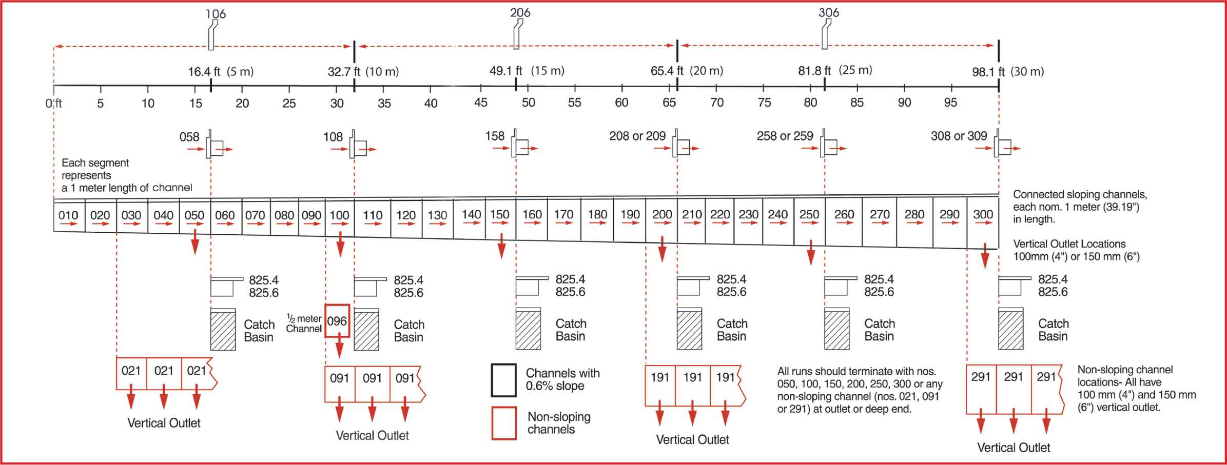
PolyWall I and II Sidewall Extensions allow the designer or contractor to extend a continuous- sloping channel run from 98.1 ft. (30 m) to 294.3 ft. (90 m) without necessity of a catch basin or outlet.
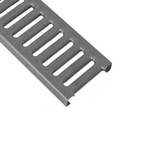
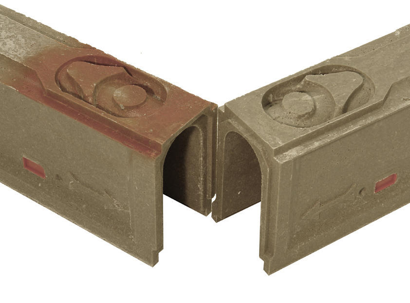
Interlocking Joints

Radius Channel

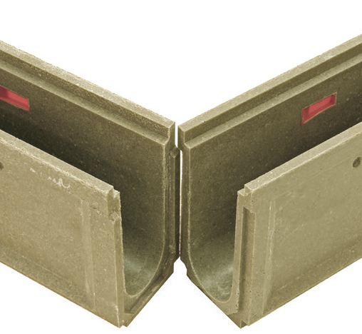
PolyDrain channels have interlocking tongue-andgroove joints that serve two important functions. First they aid in maintaining proper channel alignment during the pour. Second, they assist in securing channel connections to prevent fluid migration out of the system. ABT maintains a line of sealants that can be applied to channels when a sealed system is required.
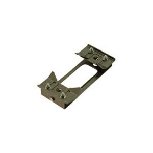
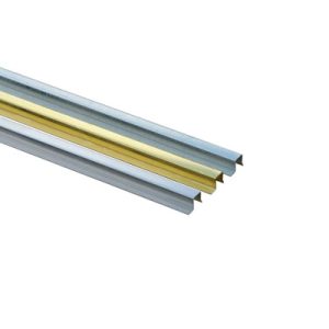
Anchoring Ribs

Radius Channel

PolyDrain channels are formed with full-length anchoring ribs on each side of the channel at the base of the side wall. These anchoring ribs provide a positive mechanical lock with

Gender Mender Outlet Channel

Radius Channel

A series of specially modified channels that addresses the difficulties encountered when two sloping channels converge where a vertical outlet is required. For every outlet channel (050, 100, 150, 200, 250 and 300), a Gender Mender channel is molded with a female interlocking joint at the low point. This feature provides proper channel alignment and eliminates field fabrication for these center draining configurations